At initial start up the ED701 will display the current firmware revision and then go to the last used Display Screen.
Press the MENU key to step through the available Display Screens SCOPE -> DATA -> MENU ->TUNER.
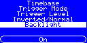
MENU Display:
While in the DISPLAY SCREEN the [MENU] key can be used to step through the available settings for the ED701 while the [OPTION] key is used to cycle through the options for each setting.
The parameters are:-
| TIMEBASE |
25uS
100uS
200uS
400uS
<1Hz
AUTO
The factory default is AUTO |
| TRIGGER MODE |
OFF – free-running mode
RISE – synchronises on rising edge of waveform
FALL – synchronises on falling edge of waveform
The factory default is RISE
|
| TRIGGER LEVEL |
Selects a voltage reference for the TRIGGER MODE. The selected value is determined by the HI-LO switch and the selected VOLTAGE RANGE
LO |
HI |
0.5V |
2V |
1.5V |
6V |
2.5V |
10V |
3.5V |
14V |
4.5V |
18V |
The factory default is 2.5V/10V
|
| INVERTED/NORMAL |
Black-On-White LCD
The NORMAL operational mode of the display is for ‘black’ pixels on a ‘grey’ background. Under certain lighting conditions you may find that inverting this makes for a more viewable display.
White-On-Blue LCD
The NORMAL operational mode of the display is for ‘white’ pixels on a ‘blue’ background. Under certain lighting conditions you may find that inverting this makes for a more viewable display.
The factory default is NORMAL
|
| BACKLIGHT |
The LCD backlight can be turned ON or OFF to assist with viewability.
This mode is not recommended when using the White-On-Blue LCD in INVERTED mode.
|
SCOPE display:
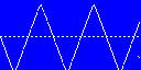
This is the default mode used to display the signal connected to the [INPUT]. As the screen on the ED701 is quite small it was decided not to clutter the display with signal data so this screen will only show the signal. To see the various values of the displayed signal you will need to select the [DATA] display.
DATA display:
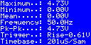
Maximum |
The maximum voltage reached by the displayed waveform |
Minimum |
The minimum voltage reached by the displayed waveform |
Mean |
The mean voltage or centre-point around which the displayed waveform is centred |
Frequency |
Shows the calculated frequency of the displayed waveform (low accuracy) |
Pk-Pk |
The peak-to-peak voltage of the displayed waveform. Equivalent to difference between Max & Min |
Trigger |
Shows the selected status of the Threshold Trigger settings |
Timebase |
Shows the selected Timebase setting |
TUNER Mode:
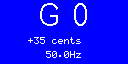
The TUNER Mode screen displays three pieces of data:-
| Note Name |
This is the musical name of the note and is expressed as a 2/3 character field of the format a x n,
Where: a = the name of the note (A, B, C, D , E F or G)
x = the accidental as either # or no data (the ED701 represents all flats as its respective sharp so, for example, B-flat is shown as A-sharp)
n = octave number (A440Hz is classified as A4)
|
| Error |
This line displays the error in cents of the input signal from its nearest musically recognised note
|
| Frequency |
This is simply the frequency of the input signal displayed as a number of Hertz
|
General Operation
In [DC Mode], set the POSITION control initially fully anti-clockwise. This will set the bottom of the screen to 0V and so will allow positive signals up to the selected [HI/LO] range to be displayed. If the signal has any negative content, then slowly adjust the [POSITION] control so that the lowest part of the signal is at the bottom of the screen.
In [AC Mode], adjust the [POSITION] control so that the signal is vertically central to the display.
If you hold down both the [MENU] key and the [OPTION] key at power on until the display shows [FACTORY RESET]. The module will automatically reset all the user settings to the factory default as described above.
|
