|
|
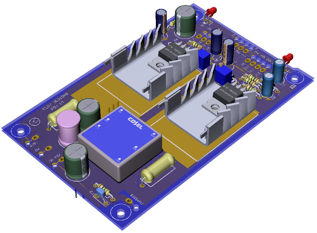
3D Model |
Overlay |
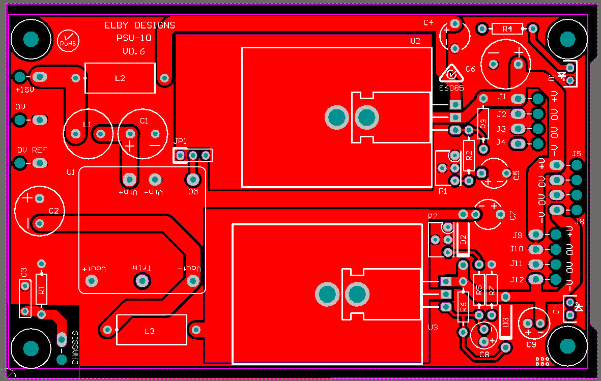
PCB Plan View |
|
|
|
|
Constructors should refer to the Component Overlays along with,
the Bill of Materials for the current value of all components, and
the General Construction Notes for general PCB assembly guidelines.
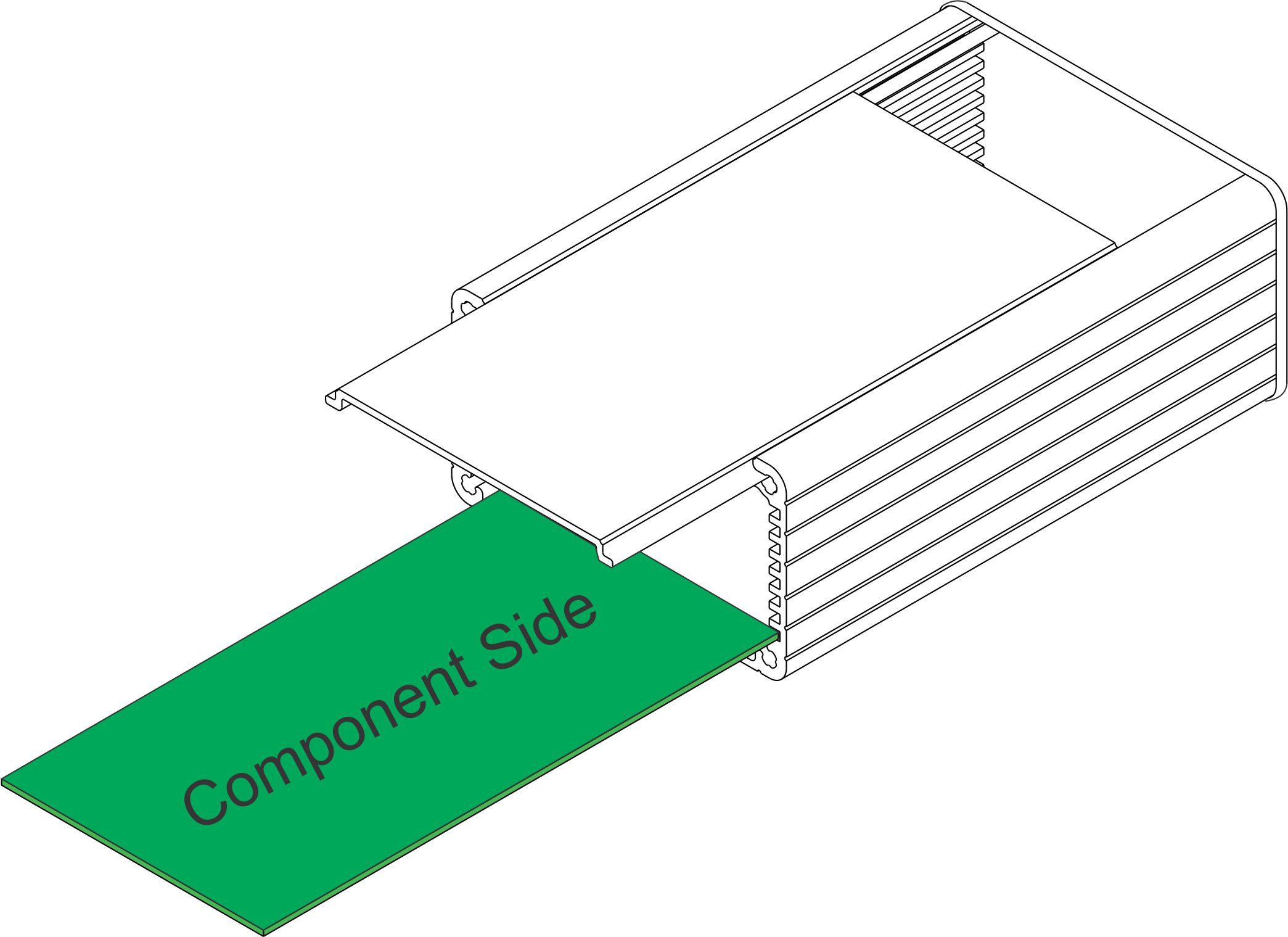
- Populate the PCB with all parts except for the LEDs. Thermal paste may optionally be applied between the regulator ICs and heatsinks, and heatsinks and PCB. When securing the heatsink insert the M3 bolt from the solder-side of the PCB
- Mount all panel components
- Preform the LEDs and insert in to the PCB folding their legs flat aginst the underside of the PCB
- Slide the PCB assembly in to the bottom slot of the enclosure and offer up the Power OUT panel to check that the LEDs are correctly positioned to allow the LED head to mount into its lens mount
- Solder tack the LEDs in to position from the component side. Then remove the PCB, fully solder the LEDs and trim their legs
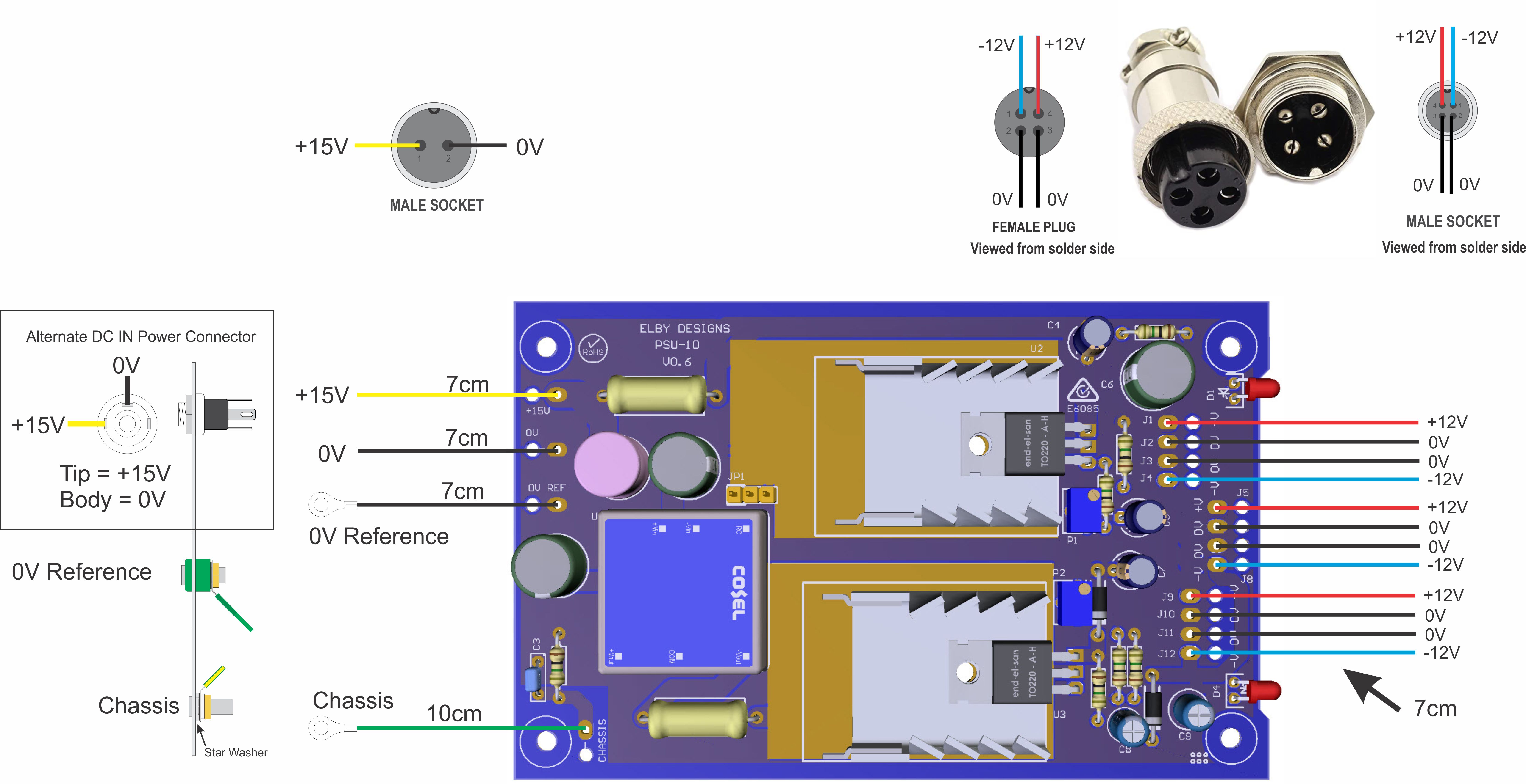
- Cut the wires as per the wiring guide
- Feed all wires, from the component side, through their respectine strain-relief pads on the PCB
- Strip approximately 3mm off each end and solder into their respective pads.
- Carefully pull each wire back from the component side to take up all slack in the wires
- When completed, check all soldering and wiring. Check that you have properly trimmed all legs on the underside of the PCB to ensure that they do not touch the enclosure, ideally there should be at least 1mm clearance
- Strip approximately 2-3mm off one end of each wire and solder to their respective pins on the components - refer to the wiring guide
- Slide the PCB assembly in to the bottom slot of the enclosure
- Power up the unit and check that all the pins on the output connectors measure correctly
- If you have the already the system you will be powering from the unit then connect it up and adjust the output rails for the correct value. If possible, you should measure the power rails at some point within the system to ensure that the system is getting optimum levels at the load. Again, if possible, check the rails at several points throughout the system and adjust the PSU-10 for optimum readings across the system.
- Slide the cover in to the enclosure and secure the front and rear panels
|
|
|


