|
Serge Dual Channel Stereo Mixer (DCSM)
This module is a variation of the Serge Dual Channel Stereo Mixer, built using the CGS101 Quad VCA and the CGS102 Equal Power Panner drivers.
Paraphrased from the 1982 Serge catalog:
The Dual Channel Stereo Mixer (DCSM) Is An Alternative Output Vca/Mixer/Panner For Two And Three-Panel Systems. The Dual
Channel Stereo Mixer is used for the standard output level control (or enveloping) and for voltage controlled panning. The DCSM has two
independent channels for stereo panning. Each channel in the DCSM has two VC inputs, one for amplitude control and one for panning. The
panning controls are opposite for the two channels, so that if a single control voltage is used, the output signals will pan in opposite
directions. Auxiliary inputs are used to feed other signals into the outputs of the module. Signals applied here will not be affected by
knobs or control voltages applied to the module. These are mainly useful for linking other mixers (either manual or voltage controlled)
to the output bus. The output is available at a pair of banana Jacks (for routing the signals to other modules within the synthesizer), and
at mini-Jacks (for connecting to external amplifiers, tape decks, and other equipment).
A little on how it works:

The schematic for Serge Dual Channel Stereo Mixer module. |
Construction
The CGS101 DCSM uses four CGS108 Serge Gain Cells as it's voltage controlled elements and two sets of CGS102 Equal Power Panner boards. These submodules should be the last things you install on the CGS101 PCB.
The unit will run on either +/-12 volts or +/-15 volts.
The first time you power it up, I would suggest you do so with 22 ohm resistors in series with the positive and negative power rails. This should save the chips if you have made a blunder.
While 100k linear pots have been specified, 50k pots will also work in this circuit.
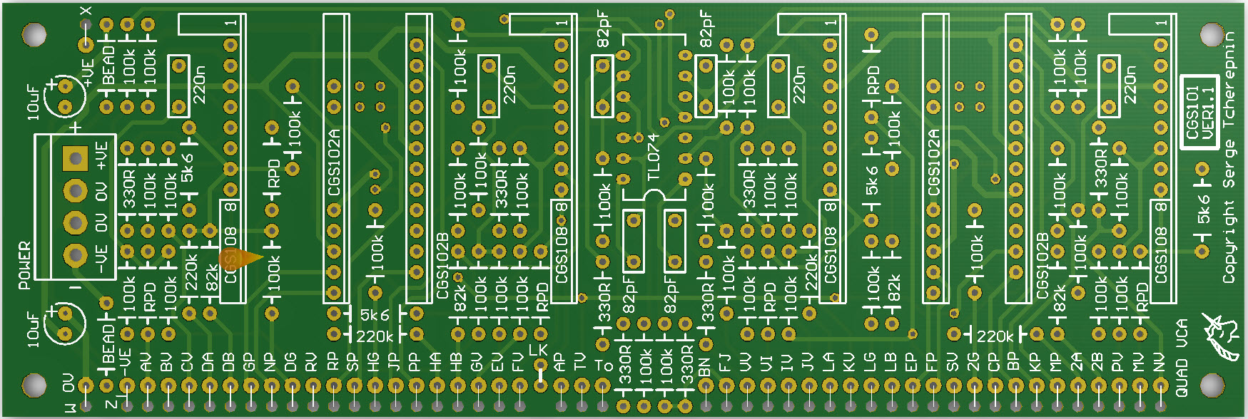
On the CGS101 VER1.0 PCB there are some corrections required.
- Four 5k6 resistors need to be installed on the rear of the PCB. Each resistor goes between pins 7 (CV) and 8 (0V) of one of the CGS108 submodules.
- Two connections to each CGS102B submodule need to be reversed. Fortunately this can be done entirely on the rear of the PCB by cutting the tracks in the areas shown in light green on the diagram below. After some solder mask is scraped from the remaining track stubs, (shown in copper below) six links can be added. The four links shown in blue can actually be replaced with two short lengths of component wire offcuts. The two links shown in purple are best if done with insulated wire as they pass over other pads.
- Two wires need to be connected to pads directly below the submodules. See the diagram for details.
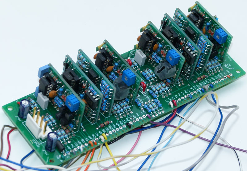
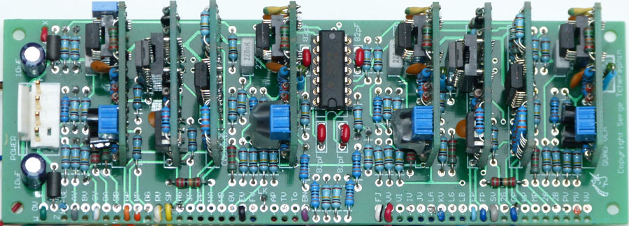
The CGS101 loaded with eight sub modules.
There may be some confusion regarding the panel layout and marking of this module. There are two input channels, and two output channels. The input channels are called Channel 1 (on the left) and Channel 2 (on the right). Above them are the two output channels, each with an auxiliary input and a pair of outputs, with the left channel to the left, and the right channel to the right.
Take care not to confuse Channel 1 with the Left output channel, or Channel 2 with the Right output channel.
| PAD ID | Function |
| CV | Aux in, Left output channel |
| RV | Signal in, Channel 1 |
| RP | Gain CV for Channel 1 |
| NP | Wiper of pan pot of Channel 1 |
| GP | Pan CV of Channel 1 |
| SP | Wiper of gain pot, Channel 1 |
| KV | Aux in, Right output channel |
| SV | Signal in, Channel 2 |
| BP | Gain CV for Channel 2 |
| EP | Pan CV of Channel 2 |
| FP | Wiper of pan pot of Channel 2 |
| CP | Wiper of gain pot, Channel 2 |
| FJ | Right output jacks |
| BN | Left output jacks |
| LK | Link these two pads |
| PV | Additional aux in, Left output channel |
| GV | Additional aux in, Right output channel |
| W | 0V power connection (connected to pots etc. as needed) |
| X | +12V power connection (connected to pots etc. as needed) |
Wiring the DCSM. Note the two wires that run under the PCB.
See the modifications diagram above for further details.
Set Up
There should be no setup required, other than to set the trimmers on the CGS108 PCBs as described here.
Notes:
- The module will work on +/-12 volts or +/-15 volts.
- PCB info: 6" x 2" with 3mm mounting holes 0.15" in from the edges..
Parts list
This is a guide only. Parts needed will vary with individual constructor's needs.
Article, art & design copyright by Ken Stone
|