|
3D Model |
Overlay |
Plan View |
Column 1 PCB |
|
|
|
Column 2 & Column 3 PCB |
|
|
|
ES21 PCB |
|
|
|
Constructors should refer to the Component Overlays along with,
the Bill of Materials for the current value of all components, and
the General Construction Notes for general PCB assembly guidelines.
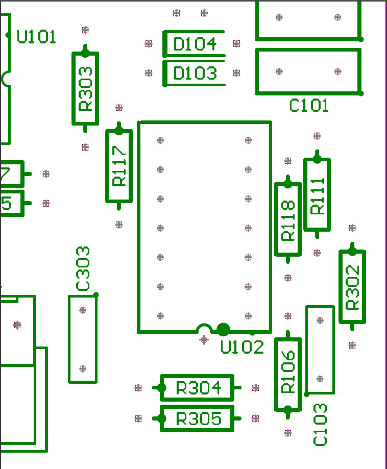
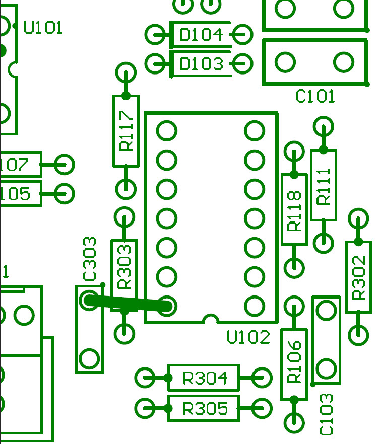
Due to an error in production there are currently two variants of the same revision of the Main PCB. Please refer to the table below to determine which variant you have and which Build Guide you should use. The identification is achieved by the location of R303.
| If your PCB has R303 in this location then continue with the instructions in the document |
|
If your PCB has R303 in this location then please follow this Build Guide |
|
- Start by preparing the 10x LEDs as per the instructions in the General Construction Notes
- Fit all components to the boards following normal assembly guidelines excluding the 10x LEDs and MANUAL pushbutton switch
- Fit the Column 2 assembly to the front panel
- Mount 5x LEDs ensuring the correct orientation of the LED wires in to the board and solder in to place
- Remove the assembly and repeat for the Column 3 assembly
- Mount the pushbutton switch on to the Column 1 assembly but do not solder
- Offer the assembly up to the front panel and secure using the supplied nuts and then solder in to place
- Mount the other assemblies on to the front panel and secure in to place
- Fit the back-board assembly ensuring the correct alignment of the IDC Receptacles in to their respective sockets
Addendum
On the V0.1 revision of the ES21 Support Board, the pad for J6_4 has been cut and should not be soldered to the connector.